Power cable and fibre sharing a trench: what does the technical standard say?
7 min read
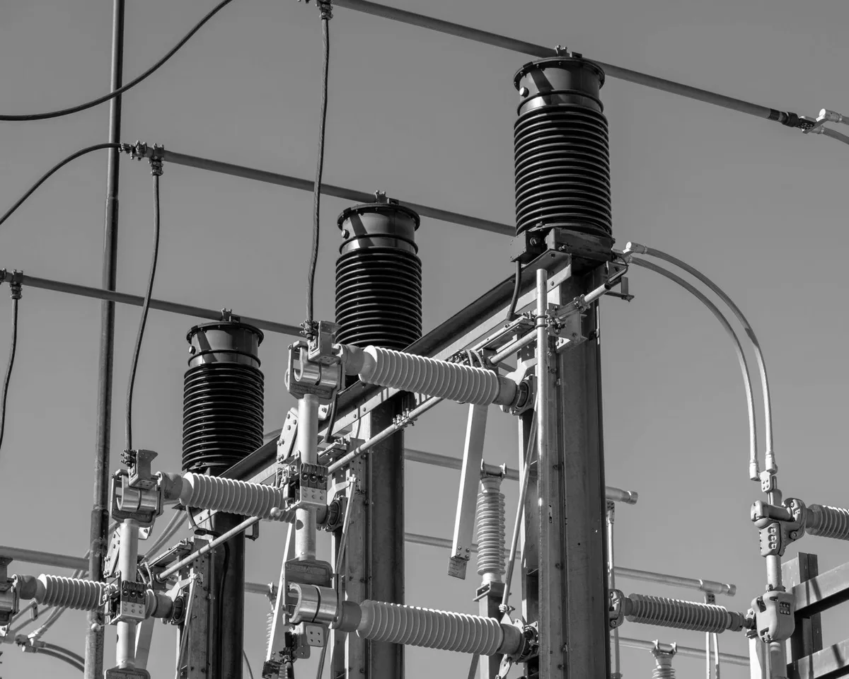
This morning we wrote about the right to slip into someone else’s trench: Regulation (EU) 2024/1309, Article 5, lets you request coordination of civil works, a month before the final project. That piece stopped there. This one starts where that one ends: the request is granted, the site is shared, and a power cable already runs — or will — in the trench you have been given. From here the Regulation no longer decides: a much older technical standard does, and the shared trench stops being a question of space. It becomes one of electricity.
What K.19 says: not clearance, an electrical distance
Recommendation ITU-T K.19, “Joint use of trenches and tunnels for telecommunication and power cables” (Geneva 1980, edition K.19 11/88, still in force), among the advantages of joint use — reduced costs, better use of underground space, less resurfacing of roads — adds one that overturns the common intuition: “the separation of power and telecommunication cables is more precisely assured.” A shared trench, done well, separates the cables better than two trenches dug without either knowing about the other: the relative position is known and documented.
Paragraph 2 sets electrical safety. Cables not easily distinguished should be clearly marked, and “power cables should generally be buried deeper than telecommunication cables.” The separation distance is not fixed: it depends on four factors — voltage and type of the power cable, type of the telecommunication cable, nature of the separating material — and K.19 refers to national standards: “the minimum distance is often stipulated in national standards.” Reduced distances are permitted only in two cases: a concentric-neutral power cable at low voltage together with an earthed-armouring telecommunication cable — a joint condition, not an alternative — or separation by concrete fillings. Where manual excavation exposes staff to danger, high-voltage cables should be protected by suitable covers.
Electromagnetic induction: when to expect it, when not
Paragraph 3 sets out three situations in which the risk is especially to be expected: a directly earthed neutral network; individual phase conductors run in separate cables, as in three-phase single-core cables; currents with high harmonic content. It is not expected under normal operating conditions — with phases properly arranged and transposed — or when the parallel run is short, some hundred metres. Other metallic conductors in a tunnel, such as pipework or concrete reinforcement, normally have a screening effect: determined case by case.
The danger nobody writes into a specification: earth potential rise
A second phenomenon, distinct from induction, is not covered by K.19 but by ITU-T K.8, “Separation in the soil between telecommunication cables and earthing system of power facilities” (edition K.8 11/88, Mar del Plata 1968 amended at Melbourne 1988, in force). A buried cable “without an insulating layer around the metal sheath”, near a high-voltage earthing installation, can pick up, in the event of an earth fault, part of the earth potential rise (EPR): a source of dangerous disturbance and a hazard to personnel.
The extent of the EPR zone “varies from some tens to some thousands of metres”, according to soil resistivity and the layout of the earth electrode. Here is the figure that matters: “measurements and calculation of the EPR zones are made by the power distribution authorities.” You do not produce them. The network operator does.
Table 1 of K.8 gives the distances beyond which neither calculation nor measurement is necessary, cross-referencing resistivity, neutral type and location: from 2 metres — highly conductive soil, under 50 Ω·m, urban, isolated neutral — up to 200 metres, soil above 10,000 Ω·m, rural, earthed neutral. That is not a distance: it is a two-order-of-magnitude range. Two warnings attached to the table must be read alongside the figures: Note 1 states that those values normally refer to lines and installations with a nominal voltage of 132 kV or above — not to medium-voltage distribution; Note 4, that they do not take into account hazards for people working inside the zone, because “such hazards require additional measures or precautions.” A specification that writes “adequate distance”, without resistivity and neutral type, says nothing.
Fibre as a remedy — and the trap of the metallic element
Paragraph 9 of K.8 points to the first remedy as increasing the distance; where that is not possible, it suggests insulating the cables in plastic ducts. Then the sentence that closes the loop: when the EPR is extremely high, or its zone very extensive, “optical fibre cables or radio-relay systems may be used instead of metallic cables.”
But it hides a trap. K.8 sets optical cables against metallic ones — but an optical cable with a metallic armour, strength member or metal tube, for EPR purposes is a metallic cable: it picks up potential exactly as a copper cable would. Writing “fibre optic cable” into a specification and believing the problem is solved does not solve anything inside the EPR zone: what is needed is a fully dielectric cable — no metallic element, in the armour or in the strength members — or the insulating duct of paragraph 9. It is the same principle behind the ADSS cable: a fully dielectric cable offers no conductive path along which the potential can transfer.
The other risks, and the agreement written before the site opens
Paragraph 4 lists other dangers: striking a power cable during excavation; access and isolation difficulties working in tunnels; explosions from gas leaks, where present; foul air accumulations. It asks that safe working methods be incorporated into the joint working agreement. Paragraph 5 adds disciplined cooperation, duties and responsibilities precisely defined — and measures for space limitations and later maintenance need to be agreed before the joint construction work commences, not during it.
Worth saying without irony: K.19 is a 1980 text, K.8 a 1968 one revised in 1988, both still in force — the physics of earth potential has not changed in forty years. What has changed is how often a fibre operator is in that position: Regulation 2024/1309 applies from 12 November 2025. The shared trench used to be the exception; today the Regulation encourages it.
What to write into the specification, what to verify on acceptance
- Request in writing from the electricity network operator the soil resistivity, neutral earthing type and EPR zone perimeter: without these three figures the distance cannot be chosen.
- Specify a fully dielectric cable within the EPR zone, or laying in an insulating duct.
- Fix the relative position — laying depth, power deeper — and distinctive marking, with acceptance verification before backfilling: afterwards, the depth can no longer be measured.
- Put in writing, in the joint working agreement, who does what for manual excavation near power cables, and the procedures for gas and foul air in tunnels.
- Record the parallel run as-built: length, distance, depth, type of adjacent power network.
The two axes, applied to a trench
The conditions of K.19 and K.8 do not stay recommendations to read once: in the specifications we write and verify they become verifiable lines — the written request to the electricity operator, the dielectric cable where needed, the laying depth — and acceptance checkpoints closed before backfilling, with the record and the measurement to produce on acceptance.
That data does not stay isolated. Traces, measurements and as-built of the parallel run — which runs pass close to a power line, at what distance, with what neutral type — feed into a single map of the network: an AI diagnoses the fault, the crew already knows where to act, together with CSIDIA, the group’s other company. Two modes: on-premise, on autonomous machines with no deep integration into the client’s network, or a dedicated cloud with a data centre in Italy — always with shared management.
The point.
A shared trench is not a clearance problem: it is an electrical one. Resistivity, neutral type and the EPR perimeter must come to you in writing from the electricity operator; and “fibre optic cable” on its own, inside the EPR zone, is not yet the solution.
Does your next run share a trench with a power cable, and you do not know who to ask for the soil resistivity? Talk to an engineer: the site survey comes at no cost, and the written request to the electricity operator is prepared while the site is still at project stage, not once the trench is already open.