Blown cable in a microduct: how much fill leaves room to blow it again tomorrow?
8 min read
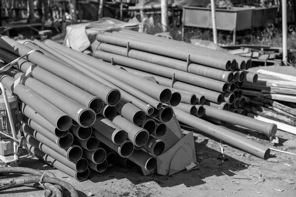
The specification says “fill ratio to standard”, the installer blows a microcable that only just fits inside the 10 mm microduct, and the test passes: attenuation within threshold, no OTDR event out of mask. Six months later a request comes in to add a second microcable to the same microduct — a new customer, one more port on the splitter — and the compressor cannot push it more than a few metres. Nobody broke anything: the first cable had already taken all the room the physics of blowing allows. The question that decides whether that route can still be used tomorrow has to be written before the first metre of microduct goes in the ground, not after.
Blowing is not a pull, it is a drag.
Compressed-air blowing is not a gentler version of pulling through a duct: it is a different physical principle. Recommendation ITU-T L.108, Optical fibre cable elements for microduct blowing-installation application, states it in its own Introduction: high-speed airflow drags the cable by viscous friction along the whole conduit, and “there is generally no pulling force at the front end of the cable; the airflow exerts a distributed force along the entire cable” — there is no pulling force applied at the front, the push is distributed along the whole length. The consequence is quantitative: “the blowing force is an order of magnitude lower than the typical force involved in other installation methods, for example pulling techniques” — an order of magnitude below the pull we have already measured in ducted installation. That is why “cables can be designed with lower tensile capabilities than cables to be pulled”: less reinforcement, thinner cables, and in principle more fibres in the same microduct.
The number quoted in specifications is not in the body of the standard.
L.108 carries its own editorial history on the cover: edition 1.0, approved on 7 July 2008, is still recorded under the dual name “ITU-T L.108/L.79”; edition 2.0, the one in force today, was approved on 16 March 2018. The ITU status page for the old designation states it without ambiguity: “Former ITU-T L.79 renumbered as ITU-T L.108 on 2016-02-15 without further modification and without being republished.” A specification that still cites “L.79” on its own is not wrong on the principle, but is chasing a number the ITU-T has not used for a decade — the same pattern, from the same 2016 renumbering wave, already seen for L.40 becoming L.302.
Clauses 1 to 8, the ones that “shall” and “should” make binding, describe fibre, blowable elements, microducts and test methods — but never fix a fill ratio as a percentage: clause 7.3 only asks that “the inner and outer diameters should be specified”, leaving the number to agreement between the parties. The 60% quoted as an “ITU-T requirement” sits elsewhere: in Appendix I, titled “Chinese experience”, and the Recommendation states it plainly at the top — “this appendix does not form an integral part of this Recommendation”. There, in a sizing table, the ratio between the microcable’s cross-section and the microduct’s inner cross-section “is generally not more than 60%”, and a note adds that it can go up to 70% “if necessary”, with a precise warning: “in this case, the blowing distance may decline”. In the same product-qualification test method (I.3.1), the range declared “reasonable” for validating a cable in the laboratory is 45-65%, with no fixed lower limit.
Pressure, too, has two different natures, and specifications and datasheets often blur them. What a microduct must withstand is a requirement in the normative body — but of another Recommendation in the same family, ITU-T L.162, Microduct technology and its applications (approved on 13 November 2016): a single microduct must have “pressure resistance greater than 10 bar”, and connectors joining microducts “should guarantee tensile strength and pressure more than 15 bar”. What is actually applied during blowing is again a figure from the same informative appendix of L.108: “generally, 15 bar max. for microduct cables and 10 bar max. for microduct fibre units”. The difference matters: a component rated above a threshold is no guarantee that the installer blew within that threshold, and it is the only one of the two figures a specification can genuinely demand as a product requirement.
Reuse is not free: the rules of subducting.
When a microduct goes into a duct that is already occupied — the technique L.162 calls subducting, designed precisely so the trench does not have to be reopened, where excavation rules require permits and reinstatement — the rules get stricter, because the remaining space is not decided by the designer but by the pipe that is already there. The standard bans microduct splices outside a manhole, with only two stated exceptions — a change of diameter, or maintenance — while elsewhere continuity must be respected “typically after laying at least 100 m in urban area and 250 m in suburban area” between one manhole and the next. And it closes the loop with a sentence that carries the whole piece: “only one microcable should be laid in each microduct. Multiple microcables or micro-elements can be installed if the microduct dimensions allow it, either upon initial installation or by later overblowing.” A second blow — overblowing — is provided for by the standard itself, but conditional: only if the microduct’s dimensions allow it. That is exactly the margin the fill ratio declared at installation decides in advance, together with the twin rule on saturation: “saturation of existing tubes is to be avoided in order to guarantee reliability and facilitate maintenance operations”.
What to put in the specification.
- The fill ratio declared in writing, section by section or by microduct type — not “compliant with ITU-T L.108”, because the standard does not fix that number: the ceiling is set by the specification, for example no more than 60%, with a documented exception only where a reduced blowing distance is declared.
- A blowing-performance test with objective metrics before handover — length reached, average speed, pressure applied — referred to methods E23 and E24 cited in clause 8.6 of L.108, not a generic “the cable went in”.
- An end cap on every free microduct end, throughout laying and until activation: L.162 makes this a de facto obligation — “end caps should always be used during the laying, storage and transportation of microducts” — to “avoid the penetration of water or dust”, because a microduct with water or dust inside changes friction and actual fill compared with the design.
- No saturation of shared infrastructure: where existing ducts are reused, microducts go into the empty pipes first, and tomorrow’s spare capacity is written down today, not discovered missing when it is needed.
- A declared reserve in every manhole — 20 to 25 extra metres of microcable for future maintenance, the figure L.162 itself gives as design practice.
How it is checked on acceptance.
Acceptance testing of a blown microduct does not end with attenuation inside threshold: it must deliver, section by section, the microduct’s actual internal diameter, the outer diameter of the microcable installed, and the ratio calculated between the two — the measured figure, not the design one. Added to this is the blowing record: pressure applied, length reached, average speed, checked against what the specification declared. Where infrastructure is reused, acceptance also checks the map of microduct splices — that they all sit inside manholes, at the declared spacing — and the reserve actually left in place. Only with these four figures can whoever comes next — for a second microcable, for a fault, for an audit — know whether they can still blow or have to reopen the trench.
The point.
The fill ratio is not a designer’s whim: it is the number that decides whether “fibre on demand” — the idea, written into L.162 itself, of laying the infrastructure today and adding cables when the customer arrives — stays a promise or becomes a constraint nobody can meet any more. The standard leaves that number to agreement between the parties: writing it down, together with the blowing test and the spare-length record, as verifiable clauses in a specifications and compliance engagement, inside an optical network design built for reuse as much as for new lay, with the test and the documentation delivered together with the work, is exactly the work we do. Every microduct, every measured fill ratio and every splice feed into the same network map — not files scattered by manhole — where an AI flags which section still has room for a second blow and which needs redesigning instead, for an operator, a data centre, an industrial site, a public administration body, a healthcare facility or a defence site. Where an AI is needed on network data, it runs within the client’s perimeter — on-premise or on dedicated cloud with a data centre in Italy — alongside CSIDIA, the group’s other company.
Are you about to write a specification for microducts going into existing pipework, or do you have to accept a route someone else has already blown? Talk to an engineer: the site visit costs nothing, and the fill ratio is measured with the same gauge we would use at acceptance.