Which of these cables is yours? You tap it, and listen from the exchange
7 min read
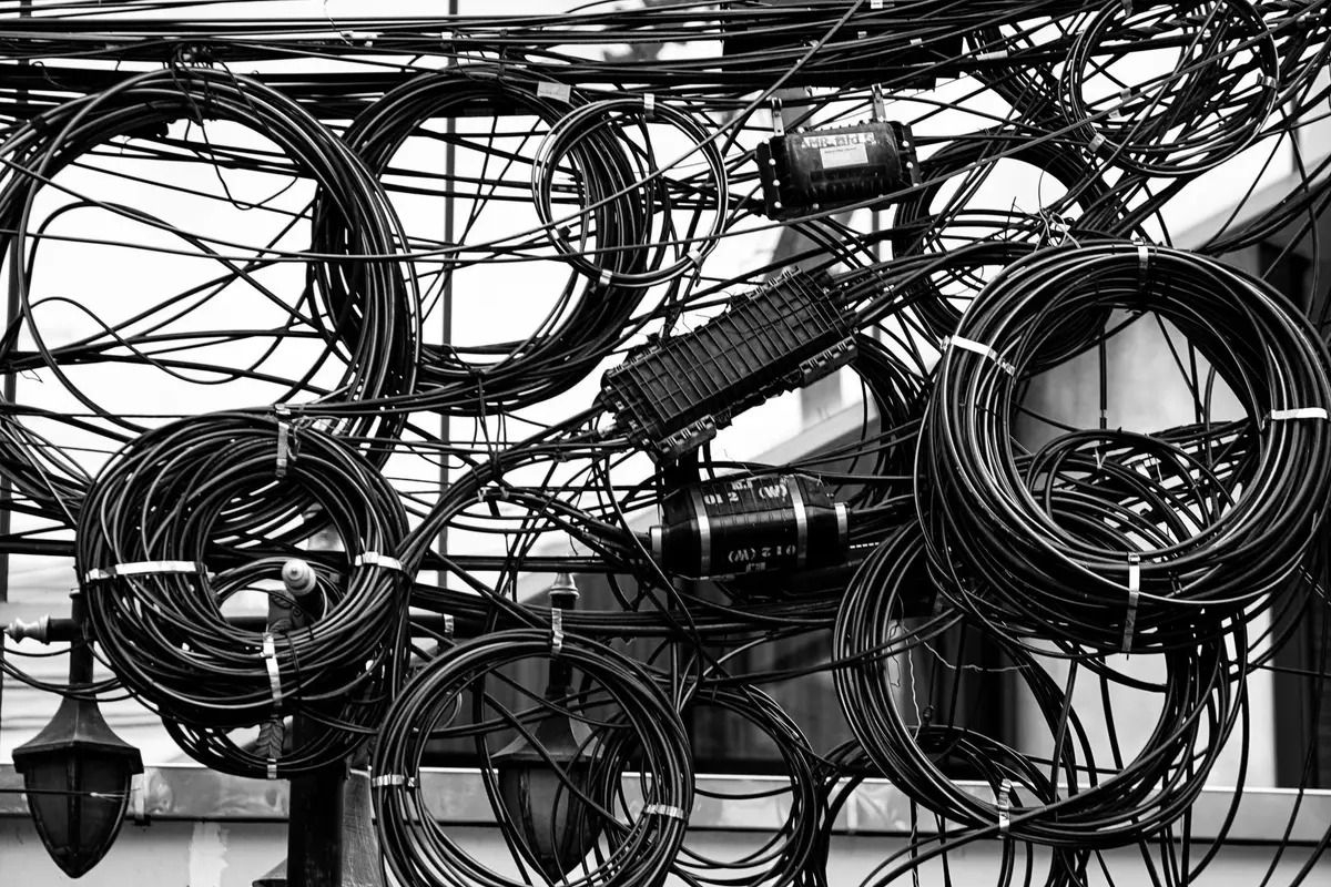
A chamber in shared infrastructure, dozens of cables from different operators: which one is ours? The answer decides whether the fault closes in an hour or a day. ITU-T Recommendation L.316, approved on 13 February 2022 by Study Group 15, standardises a method that sounds artisanal: tap the candidate cable in the field, and read the vibration at the exchange, on a dark fibre, without touching the service. The definition, clause 3.2.1: “cable identification: Distinguishing the target cable in deployed conditions containing a number of cables by applying an optical fibre sensing technique.”
Why the label is not enough
Clause 6, “Background”: “Sharing of telecommunication infrastructures such as poles, ducts, tunnels, conduits, maintenance holes and handholes, by different operators is the new norm. In shared infrastructures, optical cable identification is essential for network construction and maintenance, to quickly find the target cable among many […] and avoid incorrect handling of in-service cables.”
The traditional methods fall short, says the informative Appendix I: factory marking “could become indistinct a long time after installation, making identification difficult”; tags, missing or wrongly attached, “can cause confusion in cable identification”; RFID chip tags were introduced “To enhance passive tags.” That is exactly what a proper as-built record should prevent — and what still happens on site.
What the system has to do
Clause 7: “In cable identification, an operator of optical sensing equipment in a central office (CO) monitors the intentional vibration applied by the on-site worker.” Four requirements:
- “identify a target cable by measuring vibration by analysing a received optical signal from dark fibre”;
- “be able to monitor the intentional vibration applied to a target cable on site and also be capable of eliminating the spurious vibration created when the on-site worker handles candidate cables”;
- “employ a dark fibre of the target optical cable as a sensing fibre”;
- “be capable of being performed without degrading optical communication signals in live fibres contained in the same cable.”
The third forces a dedicated dark fibre; the fourth is why the method works on a live network.
The principle: light feels the tap
The physical mechanism, clause 8.1: “When intentional vibration is applied to a candidate cable by an on-site worker, the vibration causes fibre birefringence in the cable owing to the photoelastic effect, which creates phase disturbance or phase shift in the test light. The disturbed test light […] is received by optical sensing equipment through far-end reflection, fibre loopback or Rayleigh scattering, and the vibration signal is analysed.”
In plain terms: the tap deforms the glass for a fraction of a second, inducing birefringence through the photoelastic effect. The test light in the dark fibre picks up a phase shift — and that shift is what the equipment at the exchange measures.
The procedure, in the field and at the exchange
Clause 7.6 sets five steps. At the exchange, the operator connects the equipment to the dark fibre and launches the test light; in the field, the worker identifies the candidate cables and gets ready to strike. If too close together, they are separated first: “adjacent cables are suitably separated to prevent vibration from being transmitted between cables.” The two synchronise tap and recording — the tap is given “by different ways, including hammer, handheld motor”, says Appendix I. Once the vibration is captured clearly, “the target cable is most likely to have been identified.” Confirmation: “adjacent cables are struck to check that no vibration is captured.” To trace the whole route, the sequence repeats elsewhere.
Clause 7.1 notes that “large capacity data of the order of gigabytes is recorded even in short periods” — which is why field and exchange need a communication channel, to keep the measurement short.
How we check it
At acceptance we check that the dark fibre for identification exists in the declared cable, and is terminated as specified. We measure the return loss at the connectors along the dark fibre, because multiple reflections there create noise; and we check that the far end still provides the reflection the interferometric method depends on. Those are two opposite requirements on the same fibre, and they get verified separately. We then check that the dead zone at the equipment-to-ODF connection is known and recorded, not guessed. And we log the point where the test succeeded in the as-built record, with the correct chainage.
See the service · Talk to an engineer
Interferometric or reflectometric
The choice belongs in the specification.
The interferometric technique, clause 8.2.1: “one dark fibre is needed” in one configuration, “two dark fibres are needed, with fibre loopback at the far-end” in the other. Advantage: “high sensitivity and quick responsiveness”. Disadvantage: “the received test light generally does not have distance information, hence noise arising from environmental vibration […] cannot be eliminated easily.”
The reflectometric technique, clause 8.2.2, compares “the intensity or phase of the received Rayleigh scattering of the test light.” Advantages: the analysis also uses distance, and it is “applicable to a single dark fibre configuration without requiring far-end reflection or fibre loopback.” Disadvantages: “its relatively low sensitivity, because the vibration signal is analysed from the Rayleigh scattering, which has very small power”, and “complicated signal processing degrades responsiveness.”
The detail that contradicts a choice already made
Clause 8.2.1: “the poor reflection provided by fibre cut ends or angled physical contact (APC) connectors degrades the sensitivity of the sensing system” — enough that mirrors get introduced at the far end to compensate. The informative Appendix I states it as a practical rule: “the cable should be terminated in far end ODF using physical contact, not APC.”
APC is often the right choice because its very low reflectance cuts return noise on live fibres — but on a different plane: on the fibre dedicated to identification, it strips away the signal the interferometric system needs.
This is not a contradiction to settle for good, but a choice to make fibre by fibre, and to write into the specification: PC where the fibre serves identification, APC where it only carries traffic.
The numbers that go into the specification
- Range, clause 8.3.1: “The distance range is expected to be at least 10 km for outdoor cable identification.”
- Test light, clause 8.3.2: 1550 nm is preferred, “given its lower loss with propagation distance.”
- Return loss, clause 8.3.3: “The return loss at dark fibre connections is recommended to be higher than 40 dB”, because multiple reflections along the dark fibre create noise in the received test light; and the equipment-to-ODF connection creates a dead zone “typically of several hundred metres.”
- Tap frequency, clause 8.4: avoid the 1–90 Hz band, occupied by “traffic and wind.”
- Mechanical caution, clause 8.4: “Permanent damage to cables should, of course, be avoided.”
- Topology and scope, clauses 7.2-7.4: single star or ring topology; underground, aerial, indoor cables.
A note, clause 8.3.1: “it is preferred that customer and manufacturer confirm the conditions of cable identification” — conditions to be agreed between client and supplier, not assumed from a datasheet. And one point that covers all of them: L.316 is an international technical recommendation, not a law. Compliance is voluntary,.
Two threads, applied
First thread: dedicated dark fibre, chosen technique, minimum return loss, range, tap frequency and dead zone become verifiable lines in the specification and acceptance checkpoints, with the record a client can produce.
Second thread: the outcome of every identification — which cable, where, with which technique and margin — does not stay on a sheet of paper in a van. With CSIDIA, the group’s other company, it becomes a single map of the network on which an AI runs the diagnosis and the crew closes the fault: next time someone opens that chamber, the cable is already identified, and the tap only needs to confirm it — the same logic as the permutation frame and continuous monitoring. Within the client’s perimeter: on-premise, with no deep integration, or a dedicated cloud with a data centre in Italy, always with shared management.
Do you have cables in shared infrastructure with no dark fibre for identification? Talk to an engineer: the site visit is at no cost, and the choice between PC and APC on that fibre gets written down before the cable is laid, not on the day of the fault.