The distribution frame meets its 30 mm bend radius. Do its ports stay traceable over time?
8 min read
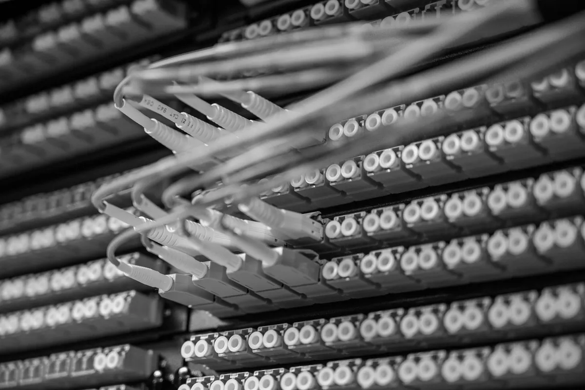
A technician needs to add a circuit to a distribution frame installed twelve months earlier. The first problem isn’t the free port: it’s reaching it. Three patch cords from later work cover it, a cable tie cinches the bundle tighter than it should, and moving just one to make room is enough for the neighbouring cord — live, in service — to drop its signal for an instant. Nobody notices: the connection comes back before any alarm fires, and nothing gets written down. The acceptance test a year earlier had certified a tidy frame. What the technician finds today grew one intervention at a time, and no one documented any of it.
The frame has a precise standard, and a name that has changed.
The recommendation that describes a distribution frame — an ODF, optical distribution frame, in industry shorthand — is ITU-T L.202 (07/2010), approved by Study Group 15. Until 15 February 2016 it was called L.50: on that day the ITU renumbered a whole cluster of recommendations on passive optical infrastructure at once, the same day L.40 became L.302 and L.79 became L.108, without ever republishing the texts under their new numbers — the document you download today still carries the L.50 header, watermarked into it. The definition, in clause 3.2.5, is the essential one: “the term ‘ODF’ refers to a frame, including the fibre organizer and the means to store and guide pigtails and cables inside the frame” — a frame, the fibre organiser inside it, and the means to store and guide patch cords and cables. The recommendation excludes active network elements such as OLTs, outdoor cabinets and customer-premises termination boxes: it covers the frame in a controlled environment, what clause 3.2.1 calls a “central office environment” — any room accessible only to qualified staff.
The minimum radius is mandatory. The port label is not.
Clause 6.1 sets a hard number: “a minimum fibre bend radius of 30 mm must be ensured throughout the entire OD(C)F” — a minimum bend radius of 30 millimetres must be maintained throughout the whole frame, single or combined (an ODCF, where several frames sit side by side to serve more than one operator). That’s a “must”: an obligation, not a suggestion. The same clause allows a tighter radius only if agreed between customer and supplier, for special fibres or applications — not as a generic shortcut.
Clause 6.1 also carries a second obligation: “the OD(C)F must allow easy identification of all connections” — the frame must allow easy identification of every connection. But when the standard gets down to how, in clause 6.6 on patch-cord storage, the register shifts: storing patch-cord slack “in an orderly manner” remains a “must”; grouping and identifying patch cords and jumpers for easy retrieval is only “recommended” — recommended, not required. That is the single most important line in the whole recommendation for anyone writing a specification: port traceability, the thing that actually matters when you need to find one fibre among hundreds, the standard suggests. It does not require it. A specification that simply cites “compliant with ITU-T L.202” leaves labelling optional by contract.
Each port gets touched on its own, or not at all.
There is a third obligation that bears directly on frame density. Clause 6.5 states: “each individual connector must be accessible, without the need to disconnect other (adjacent) connectors” — every single connector must be reachable without having to disconnect neighbouring connectors. This is the clause an overcrowded port breaches first: if reaching one fibre means pulling three others out of the way, the frame is not compliant, whatever the installed product’s datasheet claims.
Clause 6.2 adds a level of detail specifications almost never include: “it shall be possible to separate fibre circuits up to the desired separation level as defined in [ITU-T L.51]” — it shall be possible to isolate circuits up to the desired level. ITU-T L.200 (04/2003, formerly L.51, renumbered on that same 15 February 2016) defines five levels, from coarsest to finest: multiple element, single circuit, single element, single ribbon, single fibre. A specification that doesn’t state which level applies to which type of intervention leaves the crew to decide, on the day, how many fibres to disturb to reach the one they need — and that is exactly where a microbend unrelated to that day’s job gets created.
The loss figures in the appendix are an example, not a requirement.
The same L.202, in Appendices I and II, proposes thresholds for anyone who wants to verify optical stability during an intervention: up to 0.2 dB of variation during the test and 0.1 dB residual on a fibre in transit (0.3 and 0.2 dB where a connector sits in the path), up to 0.5 dB at 1310/1550 nm and 1.0 dB at 1625 nm of transient loss on adjacent live circuits when a patch cord is handled — together with an axial load test on the patch cord itself, typically between 10 and 70 newtons for ten minutes, which models exactly the pull applied by someone moving it without the right tool. Useful figures, but the same appendix says so upfront: “this appendix does not form an integral part of this Recommendation,” and “exact performance criteria are to be determined between customer and supplier” — the exact values are for customer and supplier to agree. Anyone who cites “compliant with Appendix I of L.202” as an obligation is treating an example as a requirement.
What to write into the specification.
- 30 mm minimum bend radius at every point of the frame — not just declared on a datasheet, but verified in the as-built record on every guide, mandrel and cable duct (ITU-T L.202, clause 6.1).
- Individual connector accessibility without disconnecting neighbouring ports (L.202, §6.5) — not left to whatever density the installer settles on at the time.
- A stated circuit separation level for every type of planned intervention (single fibre, single ribbon, single circuit…), per the ITU-T L.200 classification referenced by L.202 §6.2.
- Patch-cord and pigtail identification made mandatory by the specification, not by the standard: L.202 only recommends it, it does not require it. A unique code per port, tied to the as-built record.
- Intervention loss thresholds set out as agreed contractual values, not cited as an obligation under Appendix I of L.202, which remains an example.
- The frame’s as-built record updated after every subsequent intervention, not only at first installation, with a physical check at six and twelve months.
How it is verified at acceptance.
The initial acceptance test isn’t enough, for the same reason an optical acceptance test the day after installation doesn’t tell you what happens to the fibre in the years that follow: a newly installed frame is tidy by definition. A serious check measures the minimum bend radius with a gauge or a sample mandrel across a sample of points, not by eye; has the inspector — not the installer — pick any connector at random and confirms that reaching it doesn’t disturb neighbouring ports; compares the real frame port by port against the declared as-built record, not just a total port count. And above all it repeats: a re-check at six and twelve months after handover, once the first activations have already had time to pull the real frame away from the one photographed at acceptance.
The point.
A distribution frame that meets the standard on the day of acceptance and loses it one intervention at a time is not an isolated case: it’s what happens when bend radius, port accessibility and patch-cord traceability stay separate requirements written in separate places — or not written at all. That is why, when we design a distribution frame or write a compliance specification, the minimum radius, the accessibility of every port and the circuit separation level become distinct clauses, checked at acceptance with an instrument, not by eye. Every port enters the same single network map we build for a run’s as-built record: not a file ageing in a drawer, but the data an AI uses to flag which port no longer matches the last recorded intervention, before it turns into a fault someone has to hunt down by hand — for an operator, a data centre, an industrial plant, a public body, a healthcare facility or a defence site. Where AI is needed on network data, it runs within the client’s own perimeter — on-premise or on a dedicated cloud with data centres in Italy — together with CSIDIA, the group’s other company.
About to specify a distribution frame, or do you need to accept one built by someone else? Talk to an engineer: the site survey is free of charge, and the minimum bend radius gets measured with a gauge, not by eye.
Sources
- ITU-T L.202 (07/2010, formerly L.50) — Requirements for passive optical nodes: Optical distribution frames for central office environments
- ITU-T L.200 (04/2003, formerly L.51) — Passive node elements for fibre optic networks: General principles and definitions for characterization and performance evaluation