Ground clearance and sag on an aerial fibre run: who recalculates them when the load changes?
7 min read
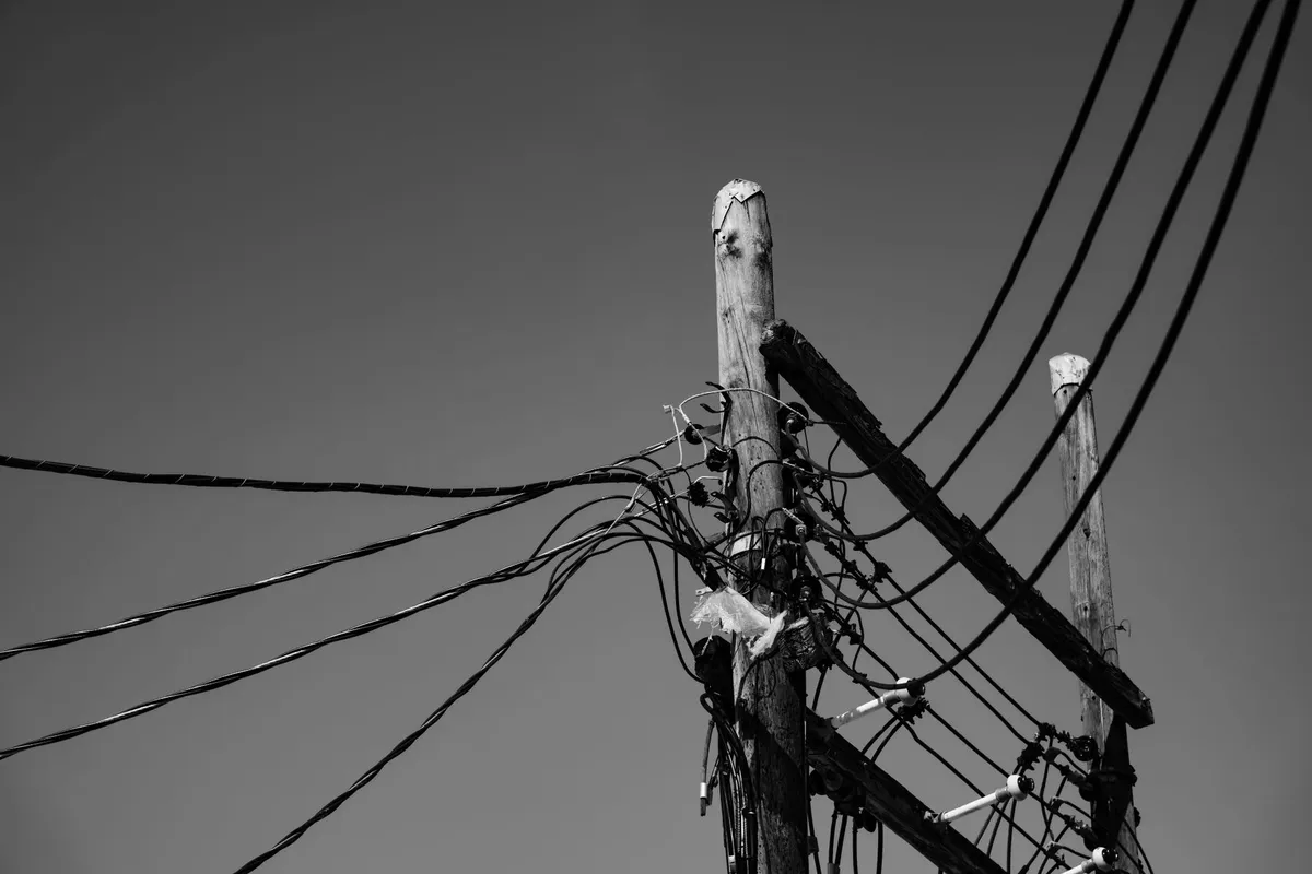
A second operator asks to hang its own cable on the same poles as an aerial line already in service. The pole owner says yes — the added weight looks negligible — but nobody recalculates the sag of the lowest span. Two winters pass, an ice load heavier than usual, and the farm machinery that crosses that stretch of country lane every summer finds, for the first time, the cable lower than it remembered. Did whoever said yes to the second operator know how much clearance would be left? And who knows it today, for that exact span?
A Recommendation for the wire, not the cable
The technical reference is ITU-T L.261, Design of suspension wires, telecommunication poles and guy-lines for optical access networks — since 15 February 2016 the designation of the former ITU-T L.89, approved on 13 February 2012 by Study Group 15; it is the same Recommendation we consult when designing an aerial run. The ITU record states, verbatim: “Former ITU-T L.89 renumbered as ITU-T L.261 on 2016-02-15 without further modification and without being republished” — same text, new designation, a single edition, in force.
The scope is narrower than the title suggests: it covers the infrastructure — suspension wire, the messenger, pole, guy-line — that supports a non-self-supporting cable, attached by the spiral-wrap technique known as lashing. ADSS cable, self-supporting and already covered elsewhere, sits outside the stated scope: the record notes it directly, “while not specifically addressed by this Recommendation, have the same issues applicable to their installation” — the same problems, a different Recommendation.
Three loads to add together, not to estimate
Clause 7.5 lists the loads the aerial infrastructure must carry together: wind, suspension-wire tension, vertical load. Wind load depends on air density, on a drag coefficient obtained by wind-tunnel testing, on wind velocity and on the exposed area of cable and wire — and the Recommendation warns that “ice accretion to the cable and suspension wire may increase in their profile area”: ice is not a separate load, it is a multiplier of the surface the wind strikes.
Suspension-wire tension ties sag, the sag, to span length: a smaller sag keeps the cable higher off the ground, but “this increases suspension wire tension […] and so an aerial infrastructure with greater mechanical strength is required” — a technical trade-off, not a figure to be lowered at will at design stage. And it is a permanent tension, not the peak measured during duct pulling: here the load stays, day and night, for the whole life of the span. Vertical load on the pole adds together the weight of the pole, “weight of snow and ice adhering to telecommunication pole”, the vertical component of guy-line tension, and — an item few specifications include — “weight of workers and tools”: a technician climbing with equipment is, for the Recommendation, a design load.
Sag moves on its own; clearance does not
Sag is not a fixed figure: it reaches its maximum “at the maximum temperature or under the maximum weather loading”, while suspension-wire tension reaches its own maximum at the opposite end, “at its minimum temperature because metal contracts as the temperature falls”. These are opposite seasonal conditions, and the design must withstand both: a clearance calculated only on installation day — often mild, often windless — is not the minimum clearance that span will ever have. For ice load the Recommendation sets no single threshold: “Ice loading guidelines are generally established by local, regional, or national authorities” — the class to use at a given site is therefore a local figure to be sourced, not a universal value in the standard.
Poles, guy-lines, and the corrosion nobody inspects from the ground
Pole classification — intermediate, corner, terminal — decides where guy-lines are needed and how many. For an intermediate pole, when wind is in the highest class, the Recommendation is specific: “It is recommended that two side guy-lines be installed every two poles as long as the site condition permits it when the wind load is classified at the highest level.” The angle between pole and upper guy-line must be “more than 25 degrees”, and the anchor is chosen from three types — piton, block, spike-bolt — with the first preferred wherever ground conditions allow: “a spiky steel piton driven into the ground, is used in most cases except when the installation is on rock or when the driving action might damage existing underground installations”. Those same guy-lines, in galvanised or aluminium-clad steel, run a corrosion risk the Recommendation locates in three settings — near the coast, from salt spray; industrial and mining areas, from sulphur dioxide; hot springs and volcanic areas, from hydrogen sulphide — a reminder for the inspection register, not a substitute for one: here too, as with reopening a splice closure, almost nobody keeps count.
Where it is written how much clearance you have today
The original design calculation fixes a sag and a design clearance, but on the load assumptions — wind, ice, number of cables — in force on that day. The acceptance record, where one exists, may report the clearance measured after installation; more often it simply declares compliance without the figure. The pole register, kept by the pole owner rather than by the fibre operator, states who else is hanging on that same support, and since when — the same discipline that, for fibre, keeps a readable as-built record together. A co-utilisation agreement with a second operator fixes the authorised added weight, but rarely refers back to the calculation that weight should have triggered: the same right of access to existing physical infrastructure that covers ducts covers, on the same terms, pole lines too. The wire and guy-line data sheet states cross-section, material and allowable tension — not the actual corrosion condition, which sits, if it sits anywhere, in a separate register. The stringing crew’s field sheet records, when it does, the tension applied that day at that temperature: the figure closest to the span’s physical reality, and the easiest one to lose once the site closes.
Six different places, for telecommunications operators managing shared pole lines, and none answers alone: how much clearance is left, in that span, under today’s load.
What we don’t know
Compliance with L.261 is voluntary, as with every ITU-T Recommendation: it binds only what a specification calls up by name. The formulas in Appendix I — wire length as a function of sag and span, temperature effects — sit in an appendix the document itself declares non-binding: “This appendix does not form an integral part of this Recommendation.” Useful for calculation, not a requirement. The Recommendation defers, for clearance and distances, to local regulations without naming them: we have not verified the thresholds set by Italian regulation on outdoor aerial lines — CEI or otherwise — and we do not state figures we have not read in full.
Applied to this run
First axis: the specification line does not read aerial installation to standard. It states the wind and ice load class assumed for that site, the design sag and clearance span by span, and at acceptance the actual clearance is measured, not merely declared compliant.
Second axis: design calculations, acceptance records, pole registers, co-utilisation agreements and guy-line inspections feed, with CSIDIA, the group’s other company, into a single map of the network. The diagnosis that matters is the comparison between the clearance measured today on a given span and the one recorded yesterday against the same identifier: an AI flags when a new cable, an out-of-class ice load or a corroded guy-line has eaten into the margin, and the crew steps in before whoever drives underneath finds out first. Within the client’s own perimeter: on-premise, on self-contained machines with no deep integration, or a dedicated cloud with a data centre in Italy, always under shared management.
Can you say, span by span, which load class was used in the design and how much clearance is left today at the lowest point? Talk to an engineer: the site survey is free of charge, and it produces a list of your spans with, for each one, the answer to this question — including the boxes that stay empty. It remains yours even if we don’t go on to work together.