Why does a brand-new fibre link fail its test? Look at the connector end face
6 min read
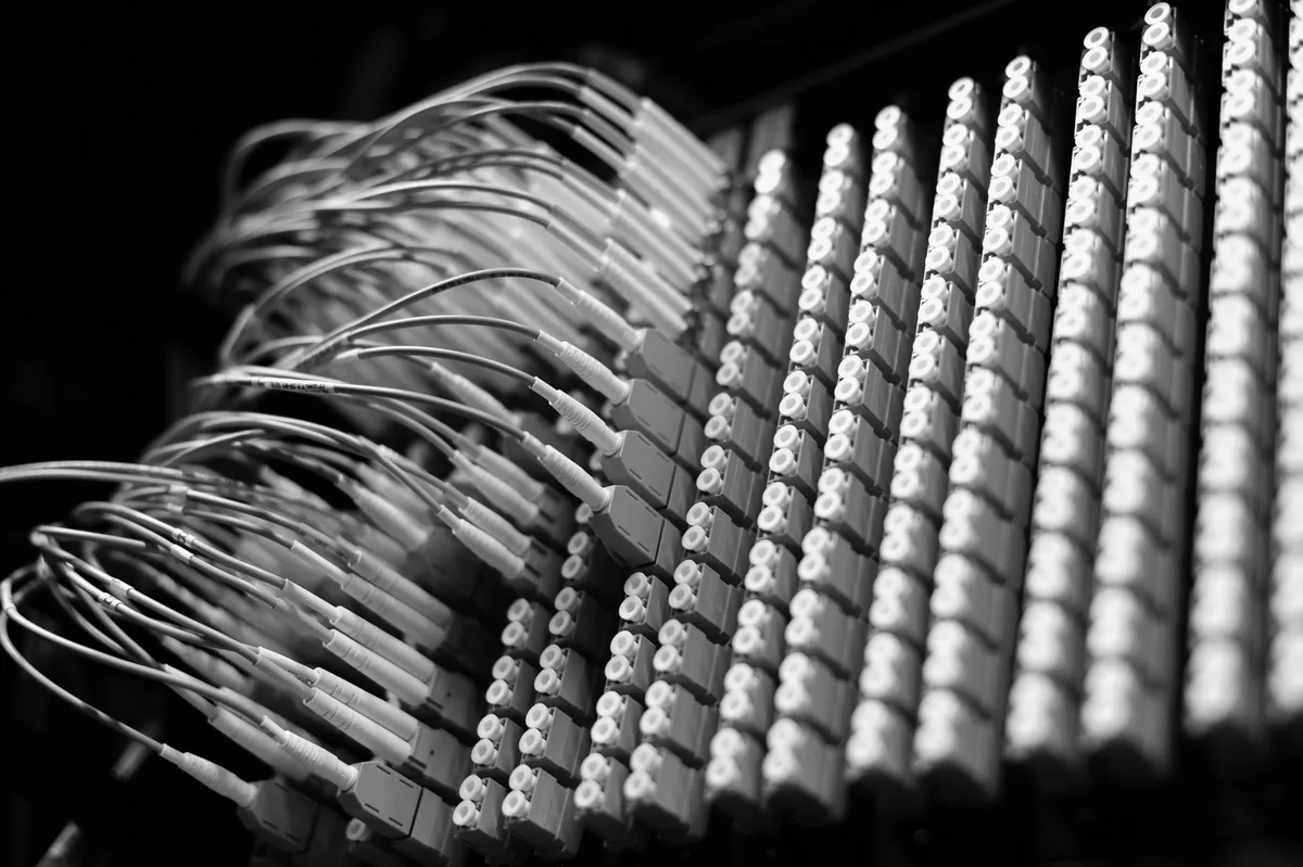
A new run, flawless fusion splices, a clean OTDR trace — and the link fails. The measurement is repeated, the splice gets the blame. Then a field microscope goes on the connector and a fragment a few micrometres across appears, sitting on the core. The commonest cause of a failed acceptance test is not an installation error: it is a dirty end face, the one thing the eye cannot see.
Why one dirty end face breaks two measurements at once.
A single-mode connector works by physical contact: the two fibres touch and light passes from one core to the other without crossing air. That is the principle behind every standardised optical interface in the IEC 61755 and IEC 63267 series, as the IEC states in the standard’s objectives.
One particle is enough to break that contact, and three things happen together.
- It intercepts the beam: insertion loss rises, and rises differently from one mating to the next.
- It opens a micro air gap: a Fresnel reflection appears at the glass-air-glass interface, so reflectance goes out of specification even when the loss still looks acceptable.
- It spreads: as the ferrule is tightened, the particle is crushed between zirconia and glass. The clean connector you have just mated is now dirty too, and often scratched.
The third point turns a nuisance into a network problem: one contaminated cord carried round the rack leaves a mark on every port it touches. Where powers are high — amplifiers, multiplexed backbones, tightly budgeted PON branches — the particle absorbs energy, heats up and can weld to the glass: at that stage there is nothing left to clean, the pigtail gets replaced. The IEC devotes an annex of its technical report on cleaning to the impact of contamination.
What the standard actually says, and what changed in 2022.
The reference is IEC 61300-3-35:2022, edition 3.0 of 16 September 2022, Visual inspection of fibre optic connectors and fibre-stub transceivers. Mind the title: until 2015 the same part was called Fibre optic connector endface visual and automated inspection — the name still quoted in plenty of specifications, and a withdrawn edition.
The standard classifies debris, scratches and defects, with separate criteria for scratches and defects, and different criteria zone by zone. Historically there were four zones: core, cladding, adhesive, contact/ferrule. Edition 3 removed the inspection requirements for zones C and D, replacing them with a generic cleanliness specification across the whole contact area — up to 250 µm in diameter for cylindrical ferrules, the entire surface for rectangular multi-fibre ferrules — and moved the outer edge of zone B from 115 µm to 110 µm, within microscope fixture tolerances.
We are not reproducing the table values: the standard is a paid publication and the thresholds depend on connector type and return loss class — edition 3 added requirements for single-mode 35 dB connectors. The criterion to remember is qualitative and does not change: the closer to the core, the less is forgiven, and on single-mode the core zone permits no defects.
Another new sentence from 2022 works as a contract clause on its own: a connector cannot be rejected merely because it fails visual inspection; measured optical performance decides. The converse holds too: inspection is in addition to attenuation and return loss measurement, not a replacement. Two distinct requirements.
The field rule: inspect, clean, re-inspect.
One line for the method statement: inspect before you connect, always. New connectors included, factory dust caps included — the cap protects against knocks, it does not certify cleanliness, and the IEC technical report on cleaning (TR 62627-01:2023) lists dust caps among the items to clean.
The cycle is inspect → clean → re-inspect, and the third step is always dropped: cleaning without re-checking means not knowing whether you removed the contamination or smeared it. On the how:
- dry first, cassette reel or stick cleaner of the right size: it resolves most cases;
- wet only if dry is not enough, always with a final dry pass: residual solvent leaves a halo that is itself a defect. High-purity isopropyl alcohol from a controlled dispenser, never methylated spirit, which contains water and additives and leaves more than it removes;
- never compressed air, cloths, cotton or ordinary paper: the can may deposit propellant and pushes dust into the adaptor; fabrics shed fibres and scratch;
- clean the adaptor sleeve too: half the contamination lives in there and returns to the next connector.
PC/UPC and APC: two geometries, two different mistakes.
Flat-polished faces (PC/UPC) and angled ones are not interchangeable. The 8° of APC are defined by IEC 61755-3-2:2024 for angled cylindrical zirconia ferrules; part 3-1, of the same date, covers the non-angled ones. At inspection the difference is practical: an angled face needs the correct tip and focus, otherwise half the image stays blurred and defects on the core disappear.
The mistake that costs most is cross-mating. A flat face pushed against an angled one never reaches physical contact: the cores graze along an edge, loss goes through the roof and so does reflection. If somebody forces the ferrule, the edge chips and the damage is permanent on both sides. The green body of an APC is a convention, not a mechanical safeguard: the wrong connector still goes in.
What to write into the specification.
Five lines that move the risk:
- end-face inspection to IEC 61300-3-35:2022 on every terminated connector, with edition and year quoted in full;
- photographic evidence per connector: the final image of the face (not the one taken before cleaning), pass/fail result, port identifier matching the as-built;
- inspection as a separate line item from OTDR and insertion loss, with a price of its own: if it is “included in the testing”, nobody does it;
- re-inspection after every disconnection following acceptance, warranty visits included;
- microscope and cleaning kit supplied by the installer, with reference cords inspected and replaced once they fall outside criteria.
The regulatory hook, for premises cabling, is ISO/IEC 14763-3:2024, edition 3.0 of 22 May 2024: among the new features are a normative inspection for cleanliness and recommended cleaning methods. It is no longer good practice, it is part of the test method. Read it alongside how to read an OTDR report and how to choose the pulse width: the same dirty end face that fails inspection also pushes the optical budget of the run out of range.
The point.
End-face inspection costs seconds per port and prevents the fault nobody can explain six months later: the cheapest check in the chain, and the first to disappear when time is short. That is why in the certifications we carry out the image of the face and its result travel with the trace and the loss value, connector by connector; the evidence archive sits wherever suits you — on-premise or on dedicated cloud, with a VPN and data centres in Italy staffed by us.
A specification to write, or an acceptance test to sign off? Talk to us: defining up front what gets inspected, to which standard and with what evidence costs far less than rebuilding a run.
Sources
- IEC 61300-3-35:2022 — Visual inspection of fibre optic connectors and fibre-stub transceivers (edition 3.0, 2022-09-16)
- ISO/IEC 14763-3:2024 — Testing of optical fibre cabling (edition 3.0, 2024-05-22)
- IEC TR 62627-01:2023 — Fibre optic connector cleaning methods (edition 3.0, 2023-01-31)
- IEC 61755-3-2:2024 — Angled 2,5 mm and 1,25 mm diameter cylindrical full zirconia ferrules (edition 2.0, 2024-04-11)